Laser Measurements 101
Part 2: How Can We Measure a Change In Frequency?
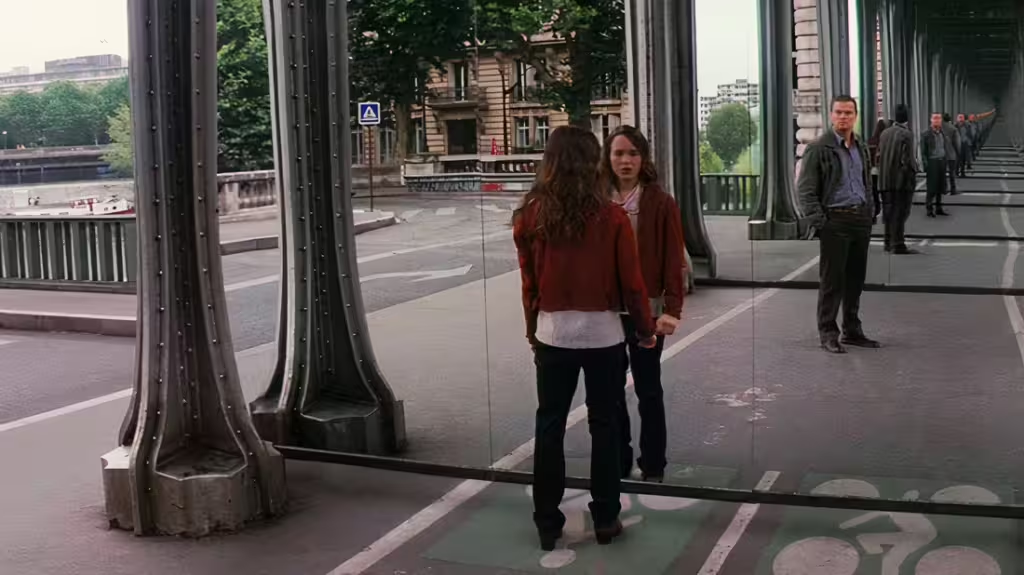
When you were a child, did you ever try to line up two mirrors perfectly so that the reflection was infinite? If you were born after 2010, you don’t have to imagine what that might look like, as the visual effects artists for Inception took care of that for you!
When I tried as a child to replicate this idea, I would immediately become frustrated that the alignment was never perfect to go all the way to infinity! In fact, no matter what I did, my eyes would block the reflection from bouncing back and forth forever!
In this blog, we’re going to discuss what would happen if you actually did line those mirrors up perfectly, and turned on a light in between them! Spoiler alert: it would get crazy. Last time, we discussed how it’s impossible to measure the transmitted and returned frequencies directly. Because they are in the THz range, we need to measure frequency changes, instead of directly measuring the transmitted and returned frequency. But what does that actually mean? How can we directly measure the \(\Delta f\), when the equation for \(\Delta f\) has two terms:
$$ \Delta f = f_1 – f_0$$
So if we can’t measure \(f_1\) or \(f_0\), how could we possibly hope to measure their difference?? The key is to use an emergent property of waves: The Superposition Principle.
If a picture paints 1000 words, then a gif must be worth a short story. The superposition principle says that if two waves (light waves in our case, but they could be any kind of wave) exist in the same space, they will add together and become a single wave.
In some sense, this means that the individual red and blue waves have ceased to exist, or at least, they cannot be measured. Only the combined result can be measured.
This is pretty convenient, we can just measure the resulting wave at a given point in space where both waves exist, and we will be measuring their sum!
Wait, didn’t we want the difference between them, and not their sum? If you can forgive a temporarily hand-waving explanation, a wave’s negative is itself but + 180 degrees out of phase.
$$ -sin(x) = sin(x + \pi) $$
So, if the waves are traveling opposite directions, then we’ll get the sum, and then the difference, as the relative phase of the waves oscillates from \(\pi\) to \(-\pi\). First, I’ll explain how we will measure this resulting wave, you will clearly see why this oscillation between sum and difference doesn’t matter at all!
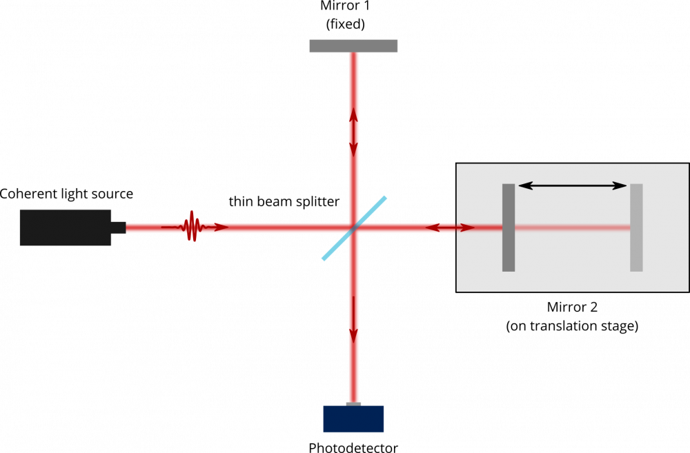
Now we just need to find some point in space where both waves exist at the same time, and measure that precise point in space. Where would that point be? Light tends to move pretty fast, so it’s a little hard to move sensors along with it. So then, one idea is to construct a mechanism to coax the light into coming to us. Like a bug to a bug zapper, maybe we can draw the photons in and point it at our sensor?
This is in fact, how many very precise laser measurements are done. You can see an illustration of this here. However, this comes with some tradeoffs. As you can imagine, the alignment of these components is very critical. That could make our lives tricky if we’re trying to measure velocity, since velocity implies things are going to be moving quite far and quite fast relative to each other!
So, this arrangement is useful in some applications, but it’s expensive, complex, and a bit overkill for our purposes! How can we simplify this a bit?
The easiest way is to avoid redirecting the light to our detector at all! Rather, let’s pick a place for the detector that we already know both of the waves will be. To find that place, let’s go back and remember how lasers work to emit light.
As you can see in the video illustration below, a laser is just 2 mirrors pointed at each other. We create a light in between those mirrors using a specific material that has 2 unique properties:
1. The material emits light when we apply electricity to it
2. The more light there is, the more light the material emits
The 1st property isn’t that special, it’s basically an LED. But the 2nd property is what makes the mirrors work their magic. By creating light and trapping it in the mirrored cavity, it can’t escape! So it bounces back and forth over and over, and because of the 2nd property, each time it travels through the medium, the material emits even more light!
That new light joins the party, which causes more light to be emitted, and as you can imagine, this situation gets out of hand very fast. Like, pico-seconds fast.
(In fact, transistor switching in a modern CPU is the only other technology that can be controlled as fast as a slow laser, and nothing responds as fast as the fastest lasers!)
If you’ve ever dabbled in controls, you immediately recognize this as a positive feedback loop. Positive feedback loops are scary, they tend to grow to infinity, or until something breaks catastrophically. So what happens? Does a black hole open up and suck the whole universe in? Well, this gain medium does emit some heat, so eventually the system overheats and melts, causing the mirrors to be not-so-mirrored.
When lasers are designed, the mirrors are perfectly engineering so that one mirror is just a tiny bit transparent.
Imagine a window with a heavily reflective tint on it. If you are outside in the broad daylight, it’s a mirror. You see nothing but a reflection! However, from the inside, you can still see outside and observe the trees, the clouds, and the sky. This is because most of the light is being reflected and does not enter into the building. However, if it’s bright enough outside, a tiny bit can get through, and that’s enough for you to see.
One of the laser mirrors is just like that. This way, once the light is strong enough, a little bit of it escapes through that window, and the light is emitted!

I will leave it as an aside for the reader to research why this design creates a highly coherent light, creating a single pure color, with many other fun properties too. For our purposes, let’s return to our goal of measuring the difference in our reflected wave, and the emitted wave.
Hopefully it’s obvious by now that the natural location to measure the light interference is inside the laser cavity itself. That is the one place that we can guarantee the emitted light will exist for sure! You might wonder, “but wait, how can we be sure that the reflected light will exist in the cavity?”. This is a great question, and this is why it’s so critical to have a relatively rough surface which will reflect the light in all directions, as we discussed in part 1! One of those directions must be the laser cavity, where the light came from! This is fantastic, it eliminates all the need for precise alignment, and complex optics like mirrors and beam splitters!
So we know where we will measure the light, but we haven’t yet discussed the purpose of this post, which is how will we measure the light?? The answer is “the same way we measure light everywhere else”, a photodiode.

A photodiode is an LED running in reverse (come at me, photodiode engineers). Instead of applying electricity to emit light out of the diode, we invert it, light hits the diode, and creates electricity.
If this sounds like a solar panel to you, that’s because it is! Solar panels are made up of photovoltaic cells, which are essentially photodiodes. In fact, if you hook up a photo diode in order to generate power, it’s called operating it in “photovoltaic” mode. Note the “volt” portion of that word? That’s the idea, generate voltage by absorbing the light energy!
However if you prefer (and we do), you can wire up a photodiode in order to measure the light instead of absorbing it! This is called using it in photoconductive mode. The name gives the hint that we will generate (an extremely tiny amount of) current, rather than voltage, and this is how we will measure our 2 waves! All we need to do is place this photodiode inside the laser cavity!
Practically, we can’t literally insert the photodiode into the laser cavity, it would be a bit too bright in there and would also destroy the key properties of the laser!
Instead, we put the photodiode behind the laser. Then, similar to the front mirror, we will also make the back mirror slightly transparent! This way, a tiny bit of light will escape onto our photodiode, and we’ll hook up some electronics to measure the intensity of this combined light.
Now we have a way to measure the frequency difference between the emitted light and the reflected light!!

Maybe now you can see why the difference vs the sum of the original superposition equation is irrelevant. The photodiode is not capable of measuring the phase of the light, it does not have a concept of positive or negative, only the intensity. So a positive intensity of 10 will measure the same voltage as a negative intensity 10, you can think of it as an absolute value measurement. This means the number of peaks will be doubled, since both peaks and valleys show up as peaks. That’s okay though, we can just divide the measured frequency by 2, and everybody’s happy!
So from part 1 we know why we need to measure the difference in frequency if we want to measure an object’s velocity using a laser, and we just discussed how to measure it using a photodiode. With just this simple single laser setup, we’re ready to measure speeds! If you want to know more about how that’s done, check out this video on the topic!